A cable tray support structure in a substation is a mechanical framework designed to hold and stabilize cable trays, ensuring safe routing, load distribution, and compliance with electrical installation standards.
Function
The support structure provides mechanical stability and alignment for cable trays, preventing sagging, vibration, and physical damage. It ensures that cables are routed securely across long spans, elevation changes, and around equipment.
Typical Locations
•Along cable trenches and galleries
•On walls, ceilings, or structural columns
•Outdoor yards and transformer bays
•Boiler areas, ESP zones, and control buildings
•Vertical risers and multi-tier tray systems
Design Elements
Support Types
•Cantilever arms for wall-mounted trays
•Channel frames for ceiling or floor-mounted trays
•Post and beam structures for outdoor racks
•Brackets and hangers for suspended trays
•Tiered frames for multi-layer tray systems
Materials
•Galvanized iron (GI), stainless steel, aluminum, or hot-dip galvanized steel
•Corrosion-resistant coatings for outdoor or chemical environments
Spacing Guidelines
•Horizontal trays: support every 1.5–2 meters
•Vertical trays: support every 1–1.5 meters
•Adjust spacing based on cable weight, tray type, and environmental conditions
Installation Considerations
•Ensure alignment and leveling to avoid cable stress
•Use vibration-resistant fasteners and anchor bolts
•Maintain grounding continuity across support points
•Allow for thermal expansion and contraction
•Avoid interference with HVAC, piping, or structural elements
•Label tray sections and supports for maintenance access
Applicable Standards
•NEMA VE 1 & VE 2 – Metal cable tray systems and installation practices
•IEC 61537 – Cable management systems
•IEEE 525 – Guide for cable tray systems in substations
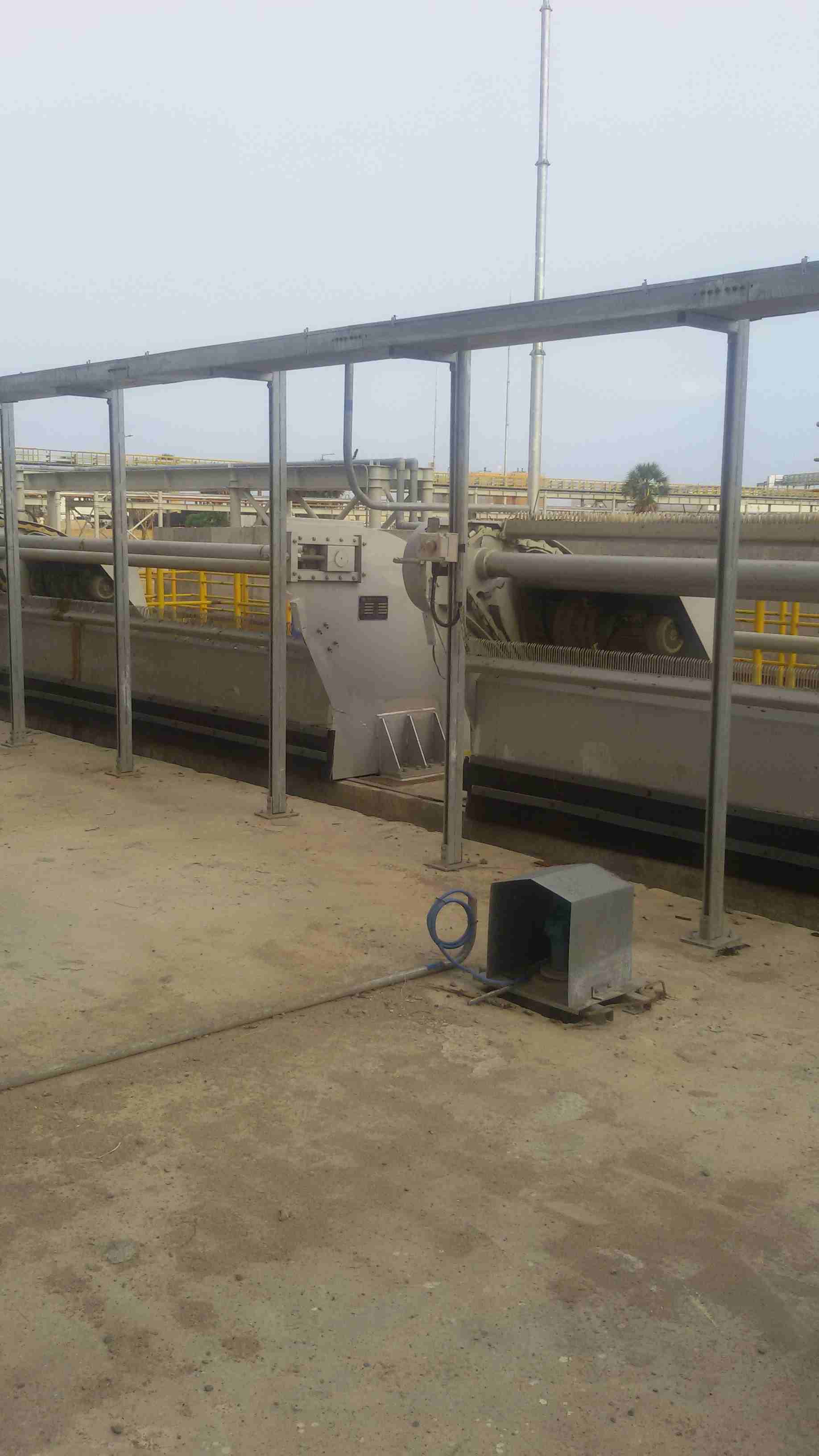
Image ID: #5
Cable Tray Support Structure
Heavy-duty steel support structure for cable trays, engineered to withstand significant cable loads and environmental factors in large-scale engineering projects.
Technical Highlights
Material / Finish
Structural Steel (I-Beam/Channel)
Key Features
Seismic braced design
Hot-dip galvanized finish typically 80 microns
Custom fabrication for site constraints
Need this engineering solution?
Contact our team for technical details or installation quotes related to this component.