A cable tray routing system in a substation is a structured network of cable trays designed to guide, support, and protect electrical cables as they travel between equipment, control rooms, and external interfaces.
Function
The routing system ensures organized, safe, and efficient cable management across the substation. It provides physical support, maintains cable separation, and simplifies future maintenance or expansion.
Key Components
•Horizontal Trays: For long runs across control rooms, galleries, or outdoor yards
•Vertical Risers: For elevation changes between floors or trench-to-panel transitions
•Elbows, Tees, Crosses: For directional changes and branching
•Supports: Cantilever arms, wall brackets, or post-and-beam structures
•Covers: For protection against dust, water, or mechanical damage
Routing Zones
•Control Room to Switchyard: For control, protection, and SCADA cables
•Transformer Yard: For HV/MV power cables and CT/PT connections
•Battery Room & DC Systems: For DC power and monitoring cables
•Cable Trenches & Duct Banks: For underground routing
•ESP/Boiler Areas: For vertical and multi-tier routing in thermal plants
Design Considerations
•Cable Segregation: Separate trays for power, control, instrumentation, and communication cables
•Bend Radius Compliance: Maintain minimum bend radius per cable type (per NEMA VE 1 or IEC 61537)
•Load Rating: Ensure trays and supports can handle the cumulative weight of cables
•Fire Safety: Use fire barriers or fire-rated trays in critical zones
•Accessibility: Design for ease of cable pulling, inspection, and maintenance
Installation Best Practices
•Route trays away from heat sources, moving equipment, and corrosive environments
•Use bonding jumpers for grounding continuity across tray sections
•Label trays and cable routes for identification and troubleshooting
•Avoid sharp bends, overfilling, or unsupported spans
•Coordinate with HVAC, piping, and structural layouts to prevent clashes
Reference Standards
•ABB Cable Tray Technical Guide
•NEMA VE 1 & VE 2 – Metal cable tray systems and installation
•IEC 61537 – Cable management systems
•IEEE 525 – Guide for cable tray systems in substations
Image ID: #6
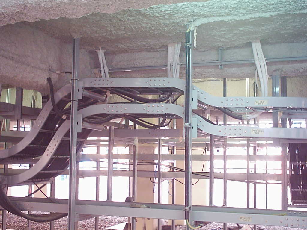
Cable Tray Routing System
Complex cable tray routing system layout showing precise alignment and integration with building infrastructure for optimal electrical distribution.
Need this engineering solution?
Contact our team for technical details or installation quotes related to this component.