
GalleryTransformer Cable Connection Setup
Back to Gallery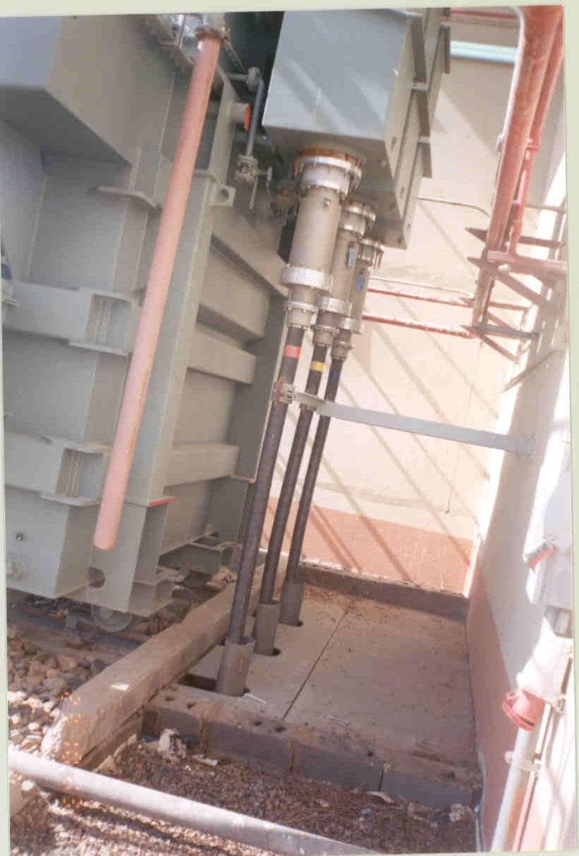
Transformer Cable Connection Setup
ksvengineering.com
Technical Overview
Substation transformer cable connection setup involves safely linking high-voltage and low-voltage cables to the transformer terminals, ensuring proper grounding, insulation, and phase alignment.
Key Steps in Transformer Cable Connection
Site Preparation
Ensure the transformer foundation is level and secure. Verify all components match the design specs.Cable Routing
Route high-voltage (HV) and low-voltage (LV) cables through designated trenches or conduits, avoiding sharp bends and mechanical stress.Termination and Insulation
- •Strip cable ends carefully
- •Use proper lugs and connectors
- •Apply heat shrink or cold shrink insulation kits
Connection to Transformer Bushings
- •HV cables connect to the primary bushings (usually marked H1, H2, H3)
- •LV cables connect to secondary bushings (marked X1, X2, X3)
- •Torque bolts to manufacturer-specified values
Grounding
Connect grounding cables to the transformer tank and ground grid to ensure safety and fault protection.Testing and Commissioning
- •Perform insulation resistance tests (megger)
- •Check phase sequence and polarity
- •Conduct load and no-load tests before energizing
Safety and Best Practices
- •Use PPE: Gloves, goggles, and arc-flash protection
- •Follow local electrical codes: Adhere to IEC, IEEE, or national standards
- •Label all connections for maintenance
- •Ensure cable ends and bushings are dry before connection