
GalleryCCCW Pump House Layout
Back to Gallery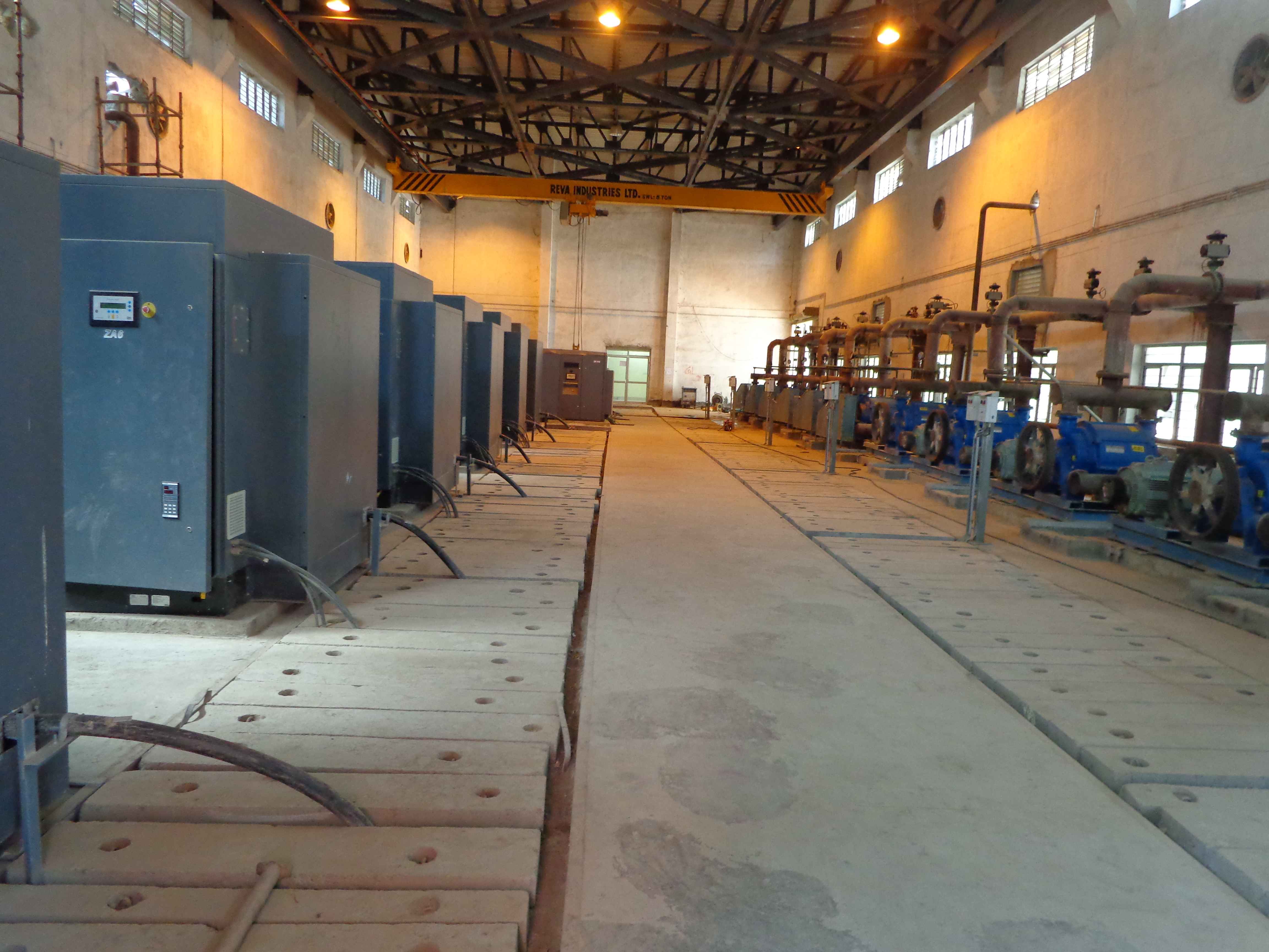
CCCW Pump House Layout
ksvengineering.com
Technical Overview
A CCCW Pump House layout defines the arrangement of pumps, piping, and electrical equipment for Component Cooling Water systems.
Layout Elements
- •Pump placement: Aligned for optimal flow and maintenance access
- •Piping routes: Suction and discharge headers
- •Electrical connections: Motor control centers and cables
- •Access aisles: Minimum 1.2m width for maintenance
Design Considerations
- •NPSH requirements: Adequate suction head for pumps
- •Vibration isolation: Flexible connections and mounts
- •Drainage: Floor slopes and sump pits
- •Ventilation: Heat removal from motors and equipment
Equipment Earthing
- •Motor frames connected to earth grid
- •Metallic piping bonded for static discharge
- •Control panels with dedicated earth bus